System Architecture
The system is structured around a dual-node embedded architecture in which functional responsibilities are partitioned according to each platform's strengths. The ESP32 operates as a Cloud Gateway (Master), orchestrating Wi-Fi connectivity, TLS-secured MQTT telemetry, and I2C bus arbitration. The FRDM-K64F operates as an Edge Sensing and Actuation Node (Slave), performing analogue-to-digital conversion of the TMP36 sensor output and driving the onboard RGB LED in response to remotely issued commands.
PubSubClient, WiFiClientSecureksdk2_0temperature/value, led/stateEnd-to-End Data Flow
The system operates two independent but concurrent data paths. The telemetry path propagates environmental measurements from the physical sensor to the cloud at a fixed 2-second cadence. The command path routes actuation instructions in the reverse direction — from a web client through the broker and down to the physical actuator.
Telemetry Path — Sensor to Cloud
Command Path — Cloud to Actuator
temperature/value MQTT topic. In the event of a bus error or conversion fault, an error payload is published instead.
Development Environments & Firmware Configuration
Firmware development for the two platforms was conducted in parallel across two dedicated IDEs, each selected to leverage native SDK and toolchain support for its respective target.
ESP32 Master Firmware — VS Code / PlatformIO
The ESP32 application was developed using VS Code with the PlatformIO extension. The firmware incorporates PubSubClient for MQTT session management and WiFiClientSecure for TLS certificate validation against the HiveMQ broker. MQTT connection parameters — port (8883), client ID, username, password, and server URL — are defined as compile-time constants. The TLS root certificate is embedded as a raw string literal (R"EOF(...)") within the source file, ensuring the TLS handshake is validated against a trusted certificate authority without relying on a system certificate store.
FRDM-K64F Slave Firmware — MCUXpresso IDE
The K64F application was developed in MCUXpresso IDE using the NXP KSDK 2.0 framework. Pin multiplexing was configured via the MCUXpresso Config Tools pin routing interface, where PTB2 was assigned to ADC0_SE12 and the I2C0 peripheral was mapped to its designated SDA/SCL lines. The ADC16 driver was activated as an SDK software component to facilitate hardware-accelerated analogue conversion. The I2C peripheral was initialised in slave mode using I2C_SlaveInit(), with a 7-bit slave address and an interrupt-driven transfer handle created via I2C_SlaveTransferCreateHandle(). Low-power wait (__WFI()) is employed within the main loop to suspend the CPU between I2C events, reducing idle power consumption.
I2C_SlaveTransferNonBlocking() registers callbacks for four distinct events: kI2C_SlaveAddressMatchEvent, kI2C_SlaveTransmitEvent, kI2C_SlaveReceiveEvent, and kI2C_SlaveCompletionEvent. This event-driven model ensures the processor remains in low-power sleep between transactions and responds with minimal latency when the Master initiates communication.
Network Provisioning — ESP Touch SmartConfig
To eliminate the need for hardcoded Wi-Fi credentials — a security anti-pattern incompatible with field deployment scenarios — the ESP32 employs Espressif's ESP Touch SmartConfig protocol for over-the-air credential provisioning. Upon initial boot, the device enters SmartConfig mode and listens for encoded UDP broadcast packets transmitted by the companion mobile application. Once the SSID and passphrase are received and validated, the ESP32 establishes the Wi-Fi association, records the assigned IP address, and proceeds to initiate the MQTT connection sequence. The terminal output confirms the provisioning lifecycle: Starting SmartConfig → SmartConfig received → WiFi connected → Attempting MQTT connection.
MQTT Telemetry & Remote Control
All cloud communication is conducted over a TLS-encrypted MQTT session on port 8883 with the HiveMQ Cloud broker. The ESP32 simultaneously maintains two roles within the MQTT protocol: it acts as a publisher on the temperature/value topic, emitting validated temperature readings at 2-second intervals, and as a subscriber on the led/state topic, receiving actuation commands from the HiveMQ Web Client.
Command Set
| MQTT Payload | Actuation | I2C Propagation | K64F Handshake |
|---|---|---|---|
| red | Illuminate red LED | ESP32 → K64F I2C write | red_OK |
| green | Illuminate green LED | ESP32 → K64F I2C write | green_OK |
| blue | Illuminate blue LED | ESP32 → K64F I2C write | blue_OK |
| off | Extinguish all LEDs | ESP32 → K64F I2C write | — |
__WFI() (Wait For Interrupt) instruction places the Cortex-M4 core into a low-power sleep state between I2C transfer events. Active peripherals are selectively gated, reducing idle current draw — a design consideration of particular relevance for battery-constrained or energy-harvesting IoT nodes.
Technical Observations & Limitations
During integration testing, the serial terminal exhibited spurious characters appended to handshake acknowledgement strings (e.g. red_OKrep·@? in lieu of red_OK). Diagnostic analysis attributed this artefact to either an absent null terminator ('\0') at the boundary of the response string, or a transmit buffer whose declared length exceeded the actual payload size — causing uninitialised memory to be serialised alongside the intended response. System functionality was unaffected; the K64F continued to process commands and the ESP32 correctly parsed the leading token. A future revision should enforce explicit null termination and constrain buffer length declarations to the precise payload width to eliminate this visual anomaly.
Hardware, Firmware & System Captures
Physical implementation, IDE configuration, network provisioning, and end-to-end data flow verification.
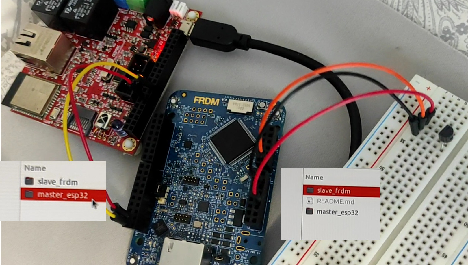
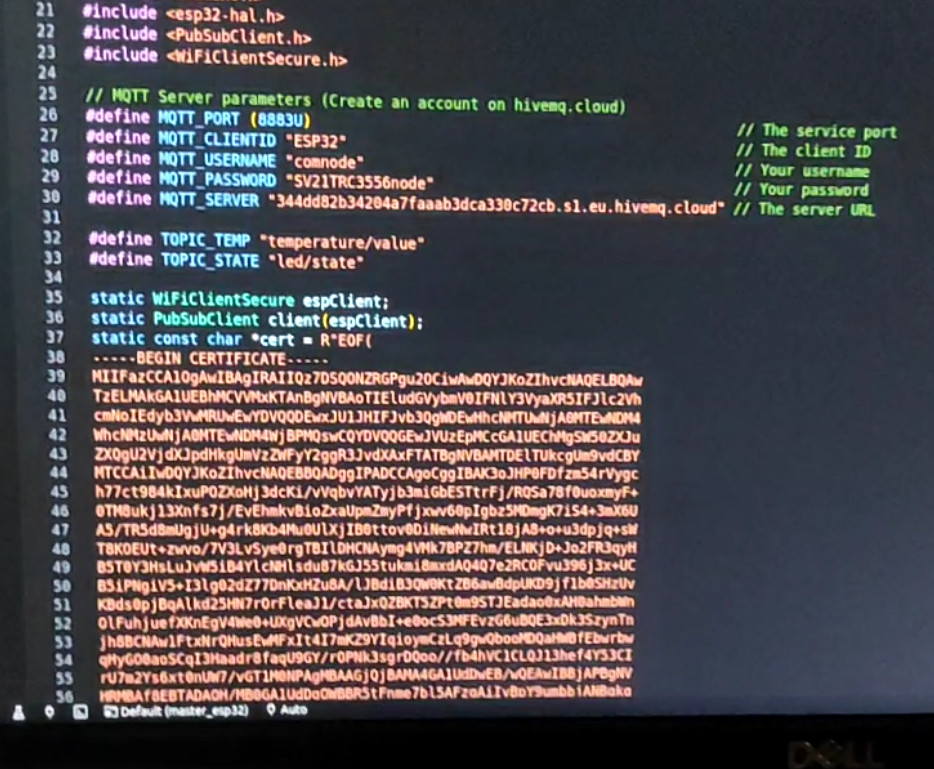
PubSubClient for MQTT session management, WiFiClientSecure for TLS certificate validation, and the I2C Master driver for periodic sensor polling. MQTT broker parameters — including the HiveMQ server URL, port 8883, and client credentials — are defined as preprocessor constants.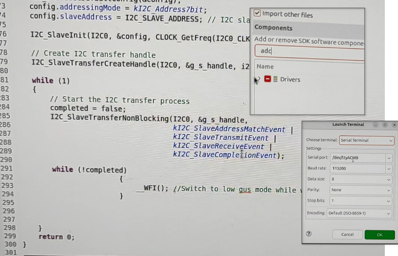
/dev/ttyACM0 to monitor the I2C callback lifecycle and temperature output in real time.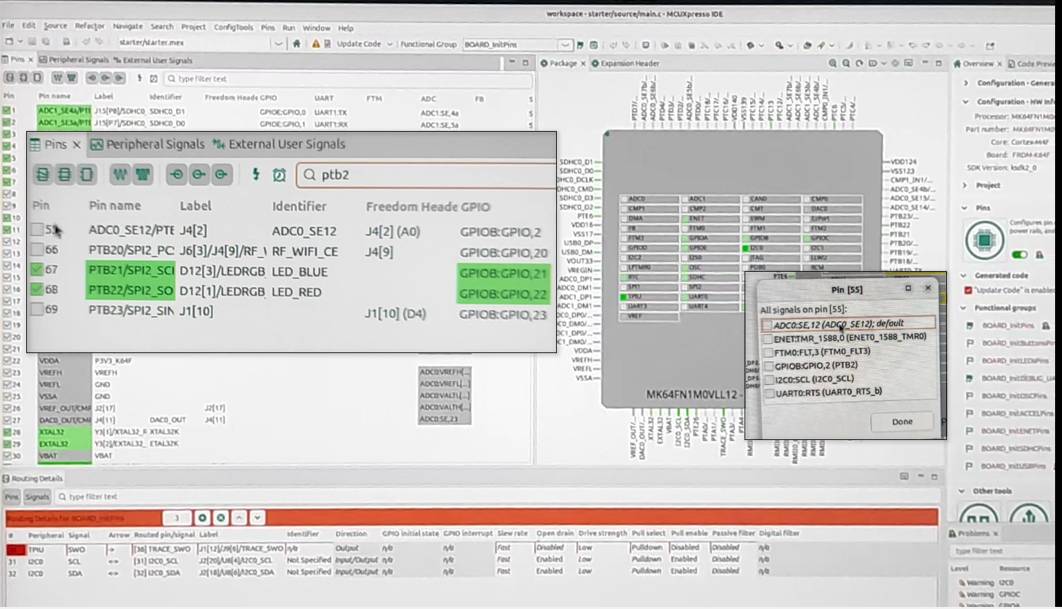
ADC0_SE12 for the TMP36 analogue input. The I2C0 peripheral SCL and SDA lines are routed to their designated expansion header pins. The non-blocking slave transfer is initialised to respond to four event flags: Address Match, Transmit, Receive, and Completion.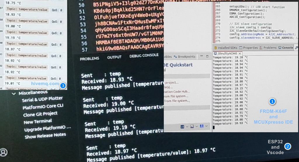
temperature/value and led/state are likewise declared at compile time.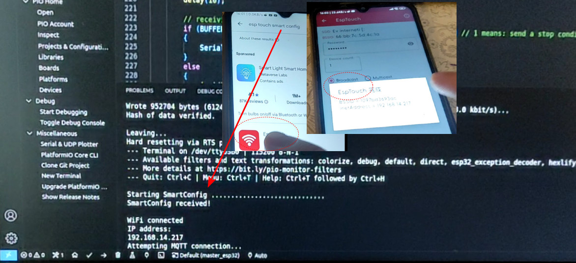
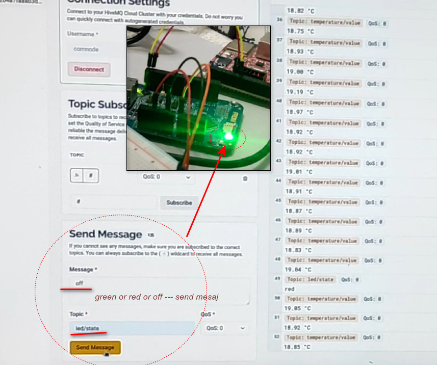
temperature/value topic stream on the right — readings in the 18–19 °C range at QoS 0. The Send Message panel (lower left) allows manual publication to the led/state topic. Commands such as green, red, or off are dispatched to the broker and subsequently relayed by the ESP32 to the K64F over I2C. The hardware photograph inset confirms the green LED responding to the corresponding command.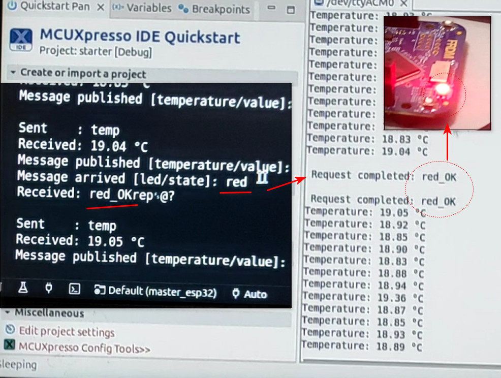
led/state topic, transmits the corresponding instruction to the FRDM-K64F via I2C, and the K64F illuminates its onboard RGB LED in red. The K64F serial terminal (MCUXpresso, right) confirms the request with Request completed: red_OK. The minor string artefact (red_OKrep·@?) visible in the ESP32 terminal is attributable to the buffer termination issue documented in §6.